Tool · Technical schematic
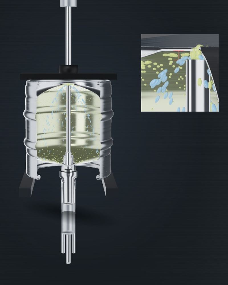
The keg stands upside down, the cleaning head pushes both valves in the spear open, and the medium runs in through the down tube and back out through the annular channel – in two pressure stages, because one alone does not reach the whole keg. Sixteen steps, traceable to a source, and with the limits above which you destroy spears.
Who runs this cleaning – and when. What is shown here is the cycle of a keg washing line in the brewery, immediately before filling. That is exactly where it belongs: sterility is not a condition a keg keeps, it is a condition for the moment. This page is a reference example of what such a cleaning cycle should look like.
Not our process. Kegs leaving our refurbishment are roughly pre-cleaned and freed of beerstone and deposits – they are not sterile and not ready to fill. The final cleaning with caustic and acid and the sterilisation are always required on the customer's side, directly before filling. The box on the overhaul page explains why.
Why two pressure stages
The medium has only one way into the keg: through the down tube. It leaves at the top end of the tube – and what happens then depends solely on the pressure being run. That is why a cleaning machine changes the pressure stage within the same step.
High pressure. The jet shoots out of the down tube as far as the sump, breaks up there and runs down the inner walls. That wets the entire shell surface, and the impact does mechanical work – that is the part of the cleaning which chemistry alone does not deliver. With caustic and acid it is exactly this phase that makes the difference between “chemically treated” and “really clean”.
Low pressure. Now the medium only just leaves the tube, falls back at the tube end and runs down the outside of the down tube, as far as the spear. This cleans the one surface the high-pressure jet systematically misses: the outside of the down tube and the transition into the spear body. Beerstone settles there by preference, because in service the tube has beer flowing around it all the time.
Run high pressure only and you get a keg with a clean wall and a coated down tube. Run low pressure only and you get the opposite. In the schematic above you can switch between them: on the four wet steps the display alternates automatically between both phases.
This description comes from our own operating practice. Specific pressure values do not appear here – they depend on the machine, the keg size and the spear type.

Limits
This is the part that appears in no cleaning guide and that you see in the workshop every day. A leading spear manufacturer names explicit upper limits in a Brewers Association seminar paper – run above them and you wreck seals and springs.
| Medium / quantity | Limit | What happens otherwise |
|---|---|---|
| Steam | 135 °C, max. 2 min | rubber decomposes, comes away from the metal core |
| Caustic | 80 °C, max. 10 min, ≤ 3 % | swelling and deformation of the seals |
| Acid | 80 °C, max. 10 min, ≤ 3 % | ditto |
| Contact force of cleaning head | max. 250 kp | explicitly named as a cause of leaking kegs |
| Clamping force | max. 2,500 N | O-ring is destroyed |
| Valve stroke, beer valve (D system) | 8 mm | “A longer stroke can damage the beer spring” |
| Valve stroke, CO₂ valve (D system) | approx. 6 mm (maximum) | overtravel damages the valve spring |
| Centring cone | replace above Ø 64.2 mm | off-centre position, cleaning flow misdirected |
| Gap, neck ring / chime | 8.5 mm ± 1.5 | reference dimension for bent necks |
| Chlorine-based cleaners | avoid | attack spear seals, corrode stainless steel |
Sources: manufacturer data from a leading spear manufacturer, published through the Brewers Association (“A Practical Approach to Refillable Kegs”) and in the Proceedings of MBAA/ASBC 2014; chlorine note from ProBrewer. The stroke and force values are documented for the D system.
Chemistry
The following values come from the cleaning whitepaper of one of the largest European keg manufacturers. They fill in the process parameters of the pool operators at exactly the points where those give only a number without a reason.
That is what the whitepaper says. The framework follows from general food hygiene law – the Regulation on good manufacturing practice for food contact materials, Framework Regulation 1935/2004 and Food Hygiene Regulation 852/2004. What follows from that in concrete terms for a keg is laid down by the filler, not by the standards body.
That is why the published parameters of the pool operators, the associations and the manufacturers differ from one another – and why every figure belongs together with a statement of who set it.
Acid concentration. One pool operator gives 0.25 to 0.4 % v/v, the manufacturer 0.2 to 0.4 %. Same upper limit, lower limit five hundredths below, in both cases without derivation.
Steam time. The pool operator gives 60 seconds. The manufacturer gives no time at all, only the “required duration” at 110 to 135 °C. Our 60-second value therefore remains a single source.
Residual condensate. Pool operator and association agree on 40 to 80 ml. The manufacturer material contains not a single value on this in sixteen documents.
Head setting
The filling and cleaning head opens the valves by pushing them in. How far it may do so is a design dimension of the spear, not a matter of adjustment. On the type A flat spear and the type G triangular spear the valve stroke is 9 to 12 mm. Filling and cleaning heads are set to the middle of that range; no head may push the valve in further.
On the type S Sankey spear it is not only the valve that moves. As it opens, the whole down tube drops by about 7 mm – which is why the bottom clearance is 14 mm there and not 9 mm as on type A. On the type D Sankey spear the down tube likewise travels downwards by the valve stroke.
That has two consequences for cleaning. The head has to match the type, otherwise it either fails to open the valves fully or pushes them beyond their stroke. And during cleaning the end of the tube sits deeper in the keg than at rest – so the low-pressure film runs down the full length of the tube.
| Spear type | Bottom clearance |
|---|---|
| A · flat spear | 9 mm |
| G · triangular spear | 9 mm |
| S · Sankey spear (European) | 14 mm |
| D · Sankey spear (US) | 14 mm |
| M · combi spear | 15 mm |
Figures from AOBAOSI, assembly drawings JM-AX-02, JM-GX-02, JM-SX-02, JM-D2-01 and JM-MX-02. The drawing for your own order is the binding one. The stroke and force values in the table above are documented for the D system.
Newsletter
About once a month: new articles, new calculators, what is moving in standards and packaging law – and offers from our range.
Type at least two characters.